Introduction
As alluded to in my previous post, I am working on a rather long term project that will (probably) be powered by an ESP32-C3. Specifically, I am working on building my own wireless speaker. And here “wireless” refers to the audio source being either Bluetooth or WiFi (i.e. a Spotify client). Unfortunately the power supply will be very much “wired”, at least for now :)
Anyway, I am developing this project in smaller pieces that I can test individually and once each one has been confirmed to work, I will squish all the PCBs together into one. So in this post I will present the amplifier board. The design has actually been ready for quite a while, I just did not have time to write it up… So by now I have already built the PCB and powered it up.
Amplifier type
Anyone who knows anything about audio amplifiers probably knows that you get two broad categories, analogue and digital. There are of course many die-hard analogue fans, but I have spent enough time slaving away at doing analogue amplifier designs that ultimately required huge heat-sinks and delivered mediocre performance. So for this project I decided to just do thing the “easy way” and simply use a so-called “Class D” amplifier.
The reality is that the math behind these digital audio amplifiers is solid and they quite simply deliver excellent sound quality in very small and very efficient packages. After some mild searching I found the Infineon Merus MA12070P appears to be an excellent candidate so I decided to go for it.
Interestingly, that amplifier comes in two flavours. One has an analogue input and the other one has a digital input. In the analogue case it simply includes an internal ADC. For a project where you have an external analogue audio source, the analogue version might make sense, but for a project like mine it would be crazy since that would just cause unnecessary conversions and lost audio quality.
The circuit
The schematic is actually quite simple, it is essentially just a whole lot of decoupling capacitors. However, the datasheet is quite specific about which decoupling needs to be where. This also depends on how you want to use the outputs of the chip. So (as always) read the datasheet carefully when doing your own design.
The layout was a bit more complicated to do as I had to make sure the high-power traces were thick enough and that the high-power decoupling capacitors were placed as close to the chip as possible. My plan is to have an amplifier with a peak power in excess of 100W, so that translates to relatively serious current… Apart from making sure that the PCB doesn’t burn up, I wanted to make sure that I did not introduce distortion due to poor decoupling. Since this is a switching amplifier, that is critical.
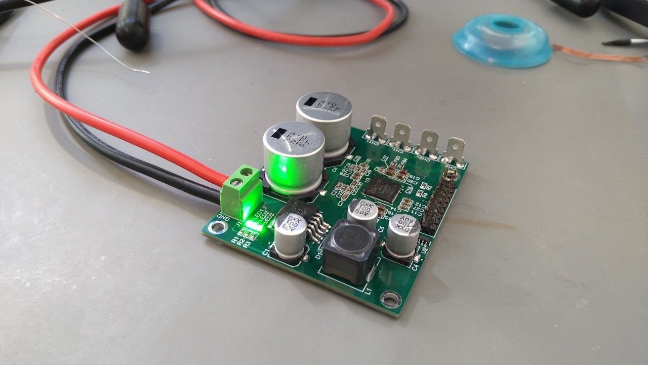
Construction and test
I used solder paste, a stencil and a reflow oven to solder all the components. Unfortunately, after a first test my power supply went into current limiting. After some inspection I noticed that the soldering on the QFN chip was a bit dodgy and that many of the joints on the other components were a bit dry. So I went over the whole board with a hot-air gun. I also gave the QFN chip some special treatment with a lot of flux and a soldering iron. This allowed the board to power on properly, but doing some continuity tests on the extension header revealed that some signal pins were still shorted. I fixed this with more flux, fresh solder and a solder wick.
A key “bug” I noticed on this design is that the LEDs are waaaay to bright. I put in relatively large resistors, but apparently they were not large enough…
Next steps
Due to the component shortage, I still have not been able to build my ESP board, so I have not tried driving the amplifier board yet. Due to a time shortage, I have also not written any firmware for that purpose yet either :). So naturally the next steps are to complete those two things and to then see if any audio comes out of the amplifier board. The absolute first steps will be to simply see if the chip responds to I2C commands.
Once I have all the electronics up and running I will need to design and construct the speaker box including the speaker drivers.
References
Naturally I took a lot of inspiration for my design from the official datasheet and reference design. However, I did need to deviate a bit because not all of the components in the reference design are available.
Comments
Comments are hosted on GitHub